


Deployments
LT Boardman Oregon: 600MW Waste-to-Energy & Waterworks Plant
Wastewater-to-Baseload Electrical Grid Power & Municipal Waterworks Plant
PHASE-1: 300 MW
PHASE-2: 500 MW
PHASE-3: 600 MW
State of Oregon / Morrow County / City of Boardman / Port of Morrow
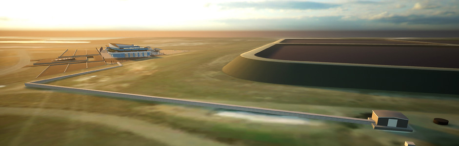
A multi-phase project of which the first 300 MW housing has been constructed on site. Shown below are 3D-modeled images of the plant's build-out and design, produced in-house by Langenburg Technologies.


CONSTRUCTION SITE PHOTOS


Located adjacent to The Port of Morrow, this project will be the first truly self-sustained regenerative power plant. It is a completely renewable system to convert waste into municipal water and energy. The core structure has been constructed as seen in the photos at left.
Construction began in early 2020, and currently on-standby pending federal, state and local dynamics. In 2019, the last coal-fired power plant in the state of Oregon was demolished, creating an urgent need for this new Langenburg baseload power plant.
FEATURES


-
BANK 1 (existing housing built on site): 300 megawatts baseload/peak power;
-
BANK 2 (next housing to be built on site) : 200 megawatts baseload power;
-
10 x 50 MW Langenburg-proprietary power units;
-
electrical load-following and 1-minute black start (without external hydraulic starter);
-
separation of pure water component from raw industrial liquid waste for municipal tap supply;
-
residual liquid waste concentrate conversion to non-carbon synthetic hydrogen-based fuel;
-
zero emissions from the turbines;
-
100% waste conversion without any residual.
FUEL-TO-POWER COMPONENT LINE
FUEL SYNTHESIZER > TURBINE > GENERATOR > CONVERTER VOLTAGE TRANSFORMER > CURRENT TRANSFORMER > BREAKER > POWER GRID


Status
System Intake Fluid Consumption/MW
System Intake Fluid Type
Project Intake Fluid Type
Fuel Type
Project Build-Phase Capacity
Turbine Type
Generator Type
Deployment Use
LT-50 MW Closed-Cycle GenSet Measure
Material Products
Construction on hold; first of 2 300 MW enclosures has been erected on site.
≈1.1 cubic meter/MW (configurable/variable by density & dissolved solids).
water, liquid, or material slurry (configurable).
Municipal and industrial wastewater sourced from treatment lagoons.
LT-Proprietary Synthetic NonCarbon Hydrogen-Based UltraFuel™ produced on-demand
Phase 1 = 300 MW / Phase 2 = 500 MW / Phase 3 = 600 MW.
Qty 6/10/12; 50 MW LT—Proprietary closed-cycle regenerative hydrodynamic.
Qty 6/10/12; 50 MW LT—Proprietary regenerative quantum-electrodynamic.
Wastewater conversion to robust baseload power transmission to consumer grid.
≈ 32’L x 10’W x 16‘H (as shown in 3D-model of plant in Port of Morrow, OR) / ≈50K lbs
Municipal water, LT UltraFuel™, baseload grid power, & oxygen water.
PHASE 1-3 SPECIFICATIONS
The liquid waste intake target is 6-10 M gals/day. Over 95% of the water content is separated from the intake stream, then treated and purified as municipal tap supply water. All remaining component byproducts from the intake are converted to non-carbon fuel used to operate an emission-free Langenburg-proprietary closed-cycle regenerative turbine. Each of the turbines are connected to Langenburg-proprietary regenerative quantum-electrodynamic power generators collectively operating at 500 MW baseload capacity, with standby excess of 50-100 MW of peak capacity. A major fraction of the plant’s capacity is also available for load-balancing. The power will be supplied local industrial users including food production and online web service farms, as well as electrical power supply for the consumer grid.
PLANT ENTRANCE GATES BUILT BY LANGENBURG
The photo below shows the plant entrance gates that were built in-house by Langenburg Technologies.

The artwork below shows how the gates will appear at the waste-to-energy plant's main entrance.


The artwork below shows the piping connection between the wastewater lagoon's pump-house, and the Langenburg waste-to-energy plant. 100% of the wastewater is converted to pure, potable water available for the City of Boardman. Electrical power will be available for transmission onto local transmission lines. Langenburg's capabilities will replace the need for a conventional wastewater treatment plant. Using Langenburg's technology, there is no chemical pre-treatment, agents, catalysts, enzymes, or micro-organisms, nor any of the typically expected time duration requirements to facilitate oxidation in open-air and solar exposure.
PROJECT DEPLOYMENT LOCATION
LT Cordele Georgia: Berverage Industrial Recycling & Ethanol Production
Beverage Wastewater-to-Baseload Power, Synthetic LT UltraFuel™ & Purified Water
PHASE-1: Water Separation
PHASE-2: Waste Conversion to Fuel
PHASE-3: Steam-Turbine Power
SYNERGY SOLUTIONS OF CRISP COUNTY
Landfill / Mixed Solid Waste Recycling / Beverage Wastewater Recycling / Ethanol Distillery
A MULTI-PHASE LANGENBURG PROJECT DEPLOYED SINCE 2019


Show below-right, are the holding tanks in which the collected/mixed beverage wastewater is pre-treated by adding organisms to facilitate fermentation. The facility has been using a distillery to take the volatile ethanol for collection, processing and sale to the petrochemical industry as a gasoline additive.
The remaining liquid after fermentation, is routed into the Langenburg wastewater-to-energy system, where the pure water is separated from this intake. The remaining concentrate of dissolved solids are converted to non-carbon synthetic fuel that replaces the need to use Diesel, propane or natural gas to operate the ethanol distillery.
The below-left, is the Langenburg system housed in a truck box, which is currently installed and connected to the LT Georgia project at Synergy Solutions of Crisp County – a recycling facility that includes the processing of wastewater sourced from the beverage industry.
Status
System Intake Fluid Consumption/MW
System Intake Fluid Type
Project Intake Fluid Type
Produced Fuel Type
Replaced Fuel Types
Project Build-Phase Capacity
Turbine Type
Generator Type
Transmission Line Interconnect
Material Products
Operational since 2019
≈1.1 cubic meter/MW (configurable/variable by density & dissolved solids).
Any water, liquid, or material slurry (configurable).
Mixed & fermented – retail beverage wastewater collected from individual sales containers.
LT-Proprietary Synthetic NonCarbon Hydrogen-Based UltraFuel™ produced on-demand
Diesel, propane and natural gas.
Phase 1; fuel production / Phase 2; LT-proprietary boilers / Phase 3; 30 MW power.
Conventional Steam Turbine.
Conventional 30 MW Magnetic Induction Generator.
Grid substation located approximately 3/4-mile from facility.
Steam-distilled ethanol, LT UltraFuel™, pure potable water, baseload power, & oxygen water.
PHASE 1-3 SPECIFICATIONS


Shown below, shows the ethanol distillers that is operated using the synthesized non-carbon LT UltraFuel™ – representing a free source of heat, that replaces the former usage of Diesel, natural gas and propane.

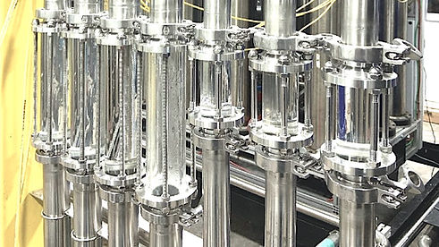
Shown below, are the transparent view-ports that reveal fluid movement and stages of processing until the fermented mixed-beverage intake is converted to synthetic non-carbon LT UltraFuel™, and pure drinking-grade water.

Shown below, is a schematic flow diagram showing inputs, outputs and processing stages. In the upper-right corner, the only intake presented is mixed beverage wastewater that has been fermented in large holding tanks.

Langenburg Phase-1 Retrofits
SEPARATE WATER FROM LIQUID INTAKE
In phase-1, Langenburg system components are utilized to separate the pure-water component from re-brewed beverage waste for production of bottling-grade drinking water. The Synergy facility collects expired and contaminated beverages, crushes the containers and recycles the packaging. Volatile ethanol is heat-distilled from the heavier fraction of the re-brew before processing by Langenburg system components.
Langenburg Phase-2 Retrofits
CONVERT RESIDUAL WASTE CONCENTRATES TO FUEL
Phase-2 implements the Langenburg Core Tech Solution™ to produce non-carbon fuel by converting residual concentrates leftover after from the water separation process. Langenburg proprietary fuel replaces Diesel as the heat source used by boilers, providing the heat source for a value-added distillation process without pollutive emissions. Because the fuel is produced on-site, fuel delivery cost is eliminated. Because the fuel is produced exclusively from waste, former use and cost of Diesel becomes obsolete. Langenburg upgrades will optimize the business model, while extending performance
and capacity far beyond any conventional process.
Langenburg Phase-3 Retrofits
USE SYNTHESIZED FUEL TO PRODUCE HEAT FOR
STEAM-POWER PRODUCTION
The final phase-3 involves use of the excess boiler steam from the distillation process to drive a steam-turbine for power generation. The power unit comprises a conventional steam-turbine and Langenburg-proprietary quantum-electrodynamic generator. Steam output from the boilers is extended by using Langenburg-proprietary nozzles and Langenburg-proprietary non-carbon fuel. Generator output is converted to standard 60Hz alternating current by use of a Langenburg-proprietary AC Converter. The facility is positioned to transmit 30-50 MW of baseload power to a substation located 3/4-mile away, for transmission onto the consumer power grid.
PROJECT DEPLOYMENT LOCATION
LT Spain: Water Purification & Oxygenation System – container installation


Built at Langenburg headquarters in Eugene Orgeon, this water purification and oxygenation system was housed for operation from within a shipping container. It was delivered as an ancillary project to the LT project deployment in Cordele Georgia.
System Intake Fluid Type
Products
Application Category
Output Capacity
Any water, liquid, or material slurry (configurable).
Langenburg medical-grade therapeutic oxygen water.
Athletic performance enhancement.
50K gal/day

PROJECT DEPLOYMENT LOCATION

Video Channel Name
LT Headquarters Eugene OR: Demonstrator Waste-to-Energy System

A MOBILE WASTE-TO-ENERGY & WATERWORKS SYSTEM


Status
System Intake Fluid Consumption/MW
Processing Capacity
System Intake Fluid Type
Output Water Quality
Configured Fuel Type
Genset Turbine Type
Turbine Inter-Cooling System
Generator Type
Black Start Cycle Duration
Evaluated Power Generation Capacity
External Converter-Transformer Voltage
System Converter-Transformer Voltage
Power Generation Mode
Current Deployment Use
End Deployment Use
LT-2 MW Compact GenSet Measure
Material Products
On standby for pre-arranged demonstration purposes since 2012
≈1.1 cubic meter/MW (configurable/variable by density & dissolved solids).
≈1.3 M gal/dy
Any water, liquid, or material slurry (configurable).
Premium oxygenated drinking water for bottling; medical-grade water.
LT-Proprietary Synthetic NonCarbon Hydrogen-Based UltraFuel™ produced on-demand.
LT-Modified Lycoming T-53 jet turbine engine.
LT-Proprietary quantum cryogenics.
LT-Proprietary baseload 2.1 MW regenerative quantum-electrodynamic.
30-Seconds with or without applied load
1.037 MW (by 1 MW ComRent resistive/reactive load bank test in 2014).
110-120 V / 220-240 V / 360-380 V / 430-400 V
110-120 V / 220-240 V / 430-400 V
Grid connected / island mode
Demonstration and evaluation of any waste conversion to energy
Municipal power generation pilot project in Stralsund, Germany.
≈ 25’L x 8’W x 8’H @ ≈5K lbs
LT UltraFuel™, baseload power, & oxygen water
SPECIFICATIONS
PROJECT'S CURRENT DEPLOYMENT LOCATION


Built at Langenburg headquarters in Eugene Orgeon, this waste-to-energy and waterworks system is used or demonstration purposes. This presentation shows photos of the unit since its completion in 2012. Since that time, many-dozens of demonstrations have been made, such as a waste conversion demonstration in September 2016 (see in Videos section of this website).
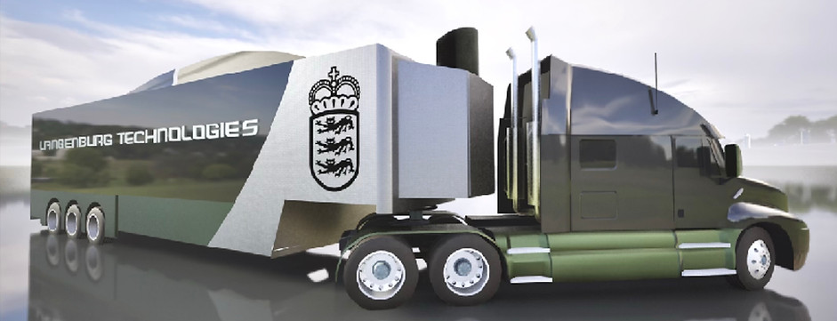
Also shown below, are artistic images of the system used for applications as a mobile emergency responder unit, and a containered waste-to-energy & waterworks plant.
ART OF LT-BRANDED MODEL OF EMERGENCY RESPONSE UNIT
ART OF EMERGENCY LT RESPONSE UNITS AT A DISASTER SITE

ART OF CONTAINERED WTE + WATERWORKS PLANT
